UPDATE: New version 2 of the altitude gear system now available.
– Now using module 1.25 gears instead of 1. Larger, stronger, more printable gear teeth.
– New design for the large altitude gears with better part split and rejoining for a more seamless gear profile.
– New roller gear mechanical design to be stronger and more accurate.
– Updated altitude motor mount and drive gear to accommodate these other changes.
Notes:
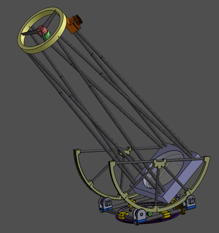
- This is a 12 (or 12.5) inch primary mirror, f/5 dobsonian telescope
- 3D Printed in 3DXTech CarbonX ezPC
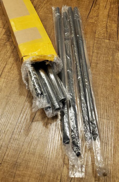
- Carbon Fiber tubes sourced from eBay sizes:
- 25x21mm
- 20x17mm
- 17x13mm
- 15x12mm
- Carbon Fiber sheet parts CNC – AliExpress Vendor
- Turntable bearing for azimuth – AliExpress Vendor
- Total Cost ~ $2000. More then a pre-made budget option, but much cheaper then a premium option.
- Bearings and Teflon (or UHMW) blocks used for altitude axis motion to provide smooth, damped motion
- Additional Teflon (UHMW) dampers on the azimuth bearing (not shown in model.)
Development
December 1, 2023
I’m in the process of designing a mostly 3D Printed 12″ dob and thinking about using 3D Printed gears for the altitude bearings. I’ve seen timing belts and pulleys as well as a couple of other methods for this, so maybe no need to reinvent the wheel here but also 3D printing is cool and I like to be a little different if I can. One advantage is we can use double-helix (herringbone gears) quite easily which should offer near zero backlash as well as being able to print just about any size gear for relatively low cost. I’m printing some sample parts to see how smoothly they roll. One potential issue I have is the Solidworks Toolbox that I’m using to generate the gears has a limit to the number of teeth so I have to use a larger module then I would think ideal. I’d like to be at 1 or 1.5 but need to go up to 2 to get the larger gear generated.
December 3, 2023
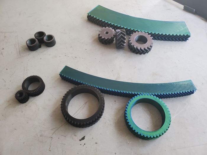
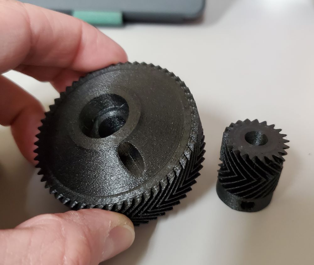
I printed several sample gears and also learned how to make the Solidworks Toolbox generate gears with more then 300 teeth so I can generate very large gears with low module. The first sample is module 2. These teeth are too large and the motion is not very smooth at all. There is a definite “clunk” as the teeth roll around. I think this would produce poor tracking results and/or excessive backlash. The second (black gears, module 1) rotate quite smoothly, but with the teeth this small I’m concerned with skipping/jumping. The third is hopefully the Goldilocks. Module 1.25. Not quite as smooth as the smaller gears, but much smoother then the large ones with still plenty of “tooth bike.” I’m thinking that when under the load of a telescope, and the slow motion of tracking, these will work well. Still a lot of work to do on the mechanical drive design of this telescope, but I think I’m confident enough with the gears to press on.

December 6, 2023
I’m working on comparing manually, properly generated gear profiles with the gears auto generated by the Solidworks Toolbox. My intention is to investigate if the “easy” and quick auto generated gears by the toolbox are good enough for this application. As I am investigating further I can’t seem to make sense of what the Toolbox is doing. The gears its generating do not made sense for the module and number of teeth specified. The diameters come out way different then they should be. Basically, it’s kind of a mess and I think I’ll abandon the Solidworks Toolbox (which is kind of what I thought would be necessary anyway.) I’m printing some more sample gears now and will post when I have some results to share. I also think I am at a state in the design where all the essential mechanical functionality is in place. Now I will proceed to work on the details of each part. Still a lot of work to do.

December 12, 2023
It took quite a bit of tinkering and printing of sample gears but I’ve come up with a workflow that is satisfactory. If anyone is interested in how to “properly” generate these gears, I followed these two tutorials:
1. To generate the proper involute tooth profile – https://thebloughs.n…-in-solidworks/
2. To generate the proper helix angle – https://youtu.be/re8…gkB7Jph3Q47eR2C
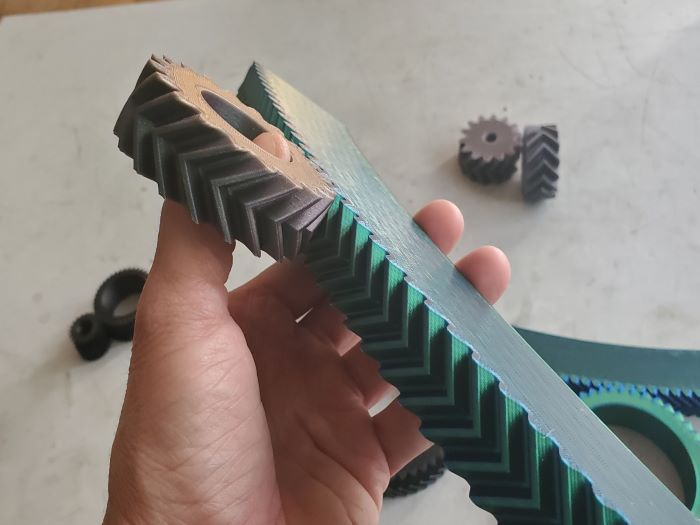
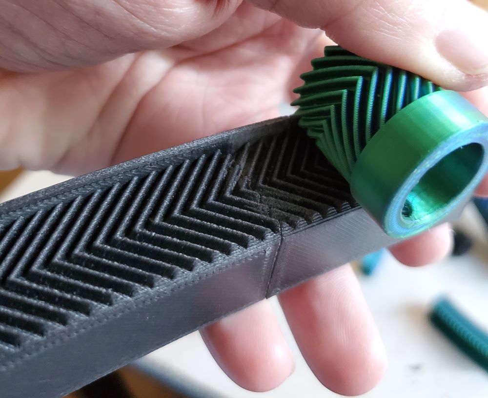
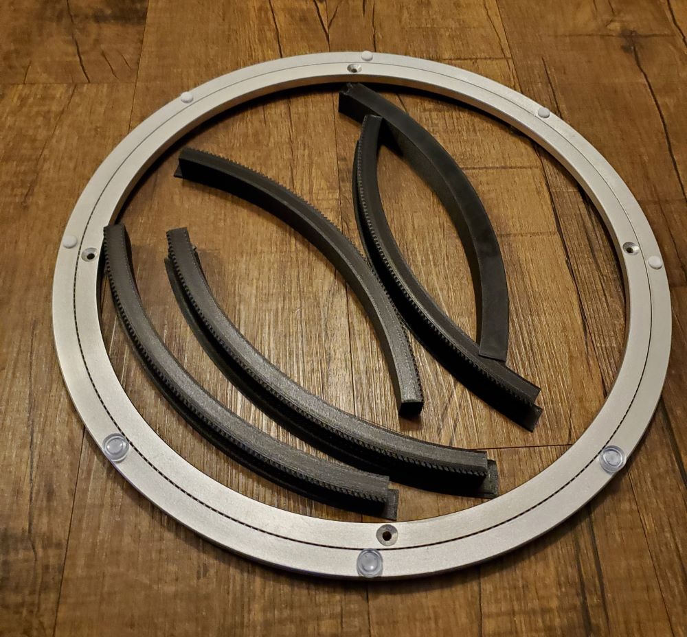
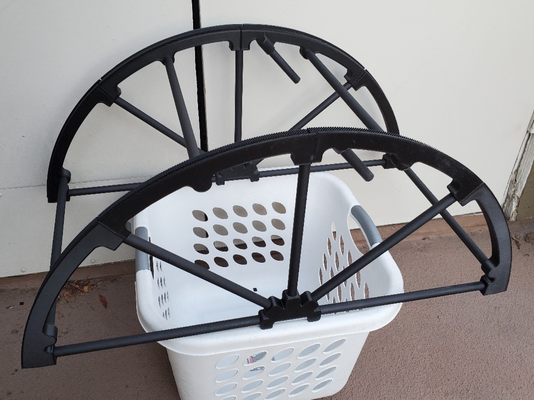
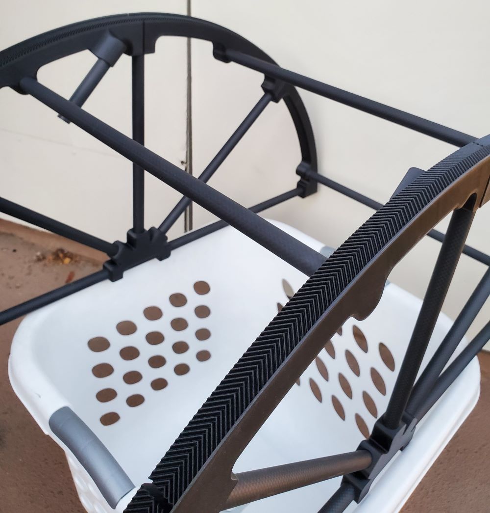
I ended up using module 1 gears, which are smaller then what I was thinking of using earlier, but they roll nice and smooth and make the math that bit much simpler when designing them. That also means that there is a LOT of teeth to generate. The Altitude gears are 795 teeth. That means a lot of processing and it does bog down Solidworks quite a bit, even with the fastest consumer desktop CPU you can get. Still, it just takes a bit of patience and they generate just fine.
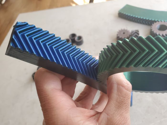
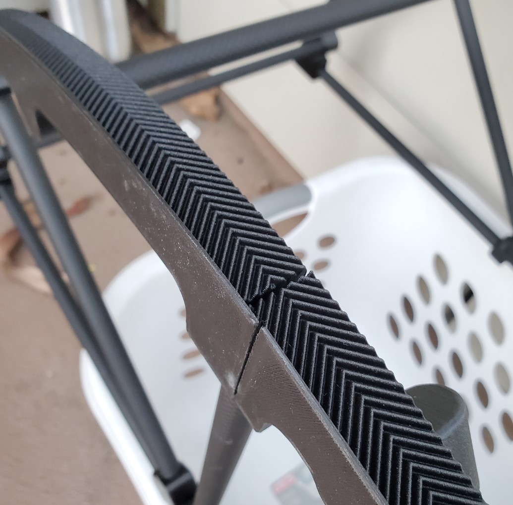
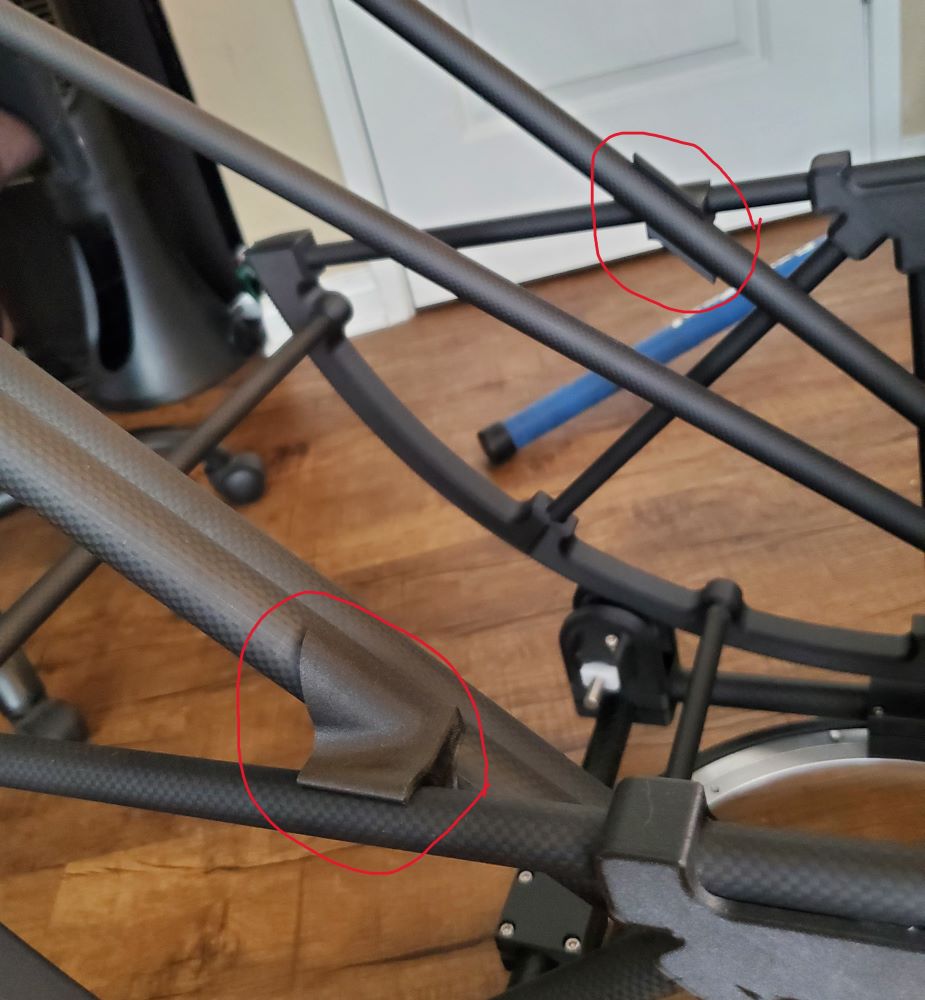
In the second image I’ve printed a couple sample sections of the Altitude gear to test the feasibility of joining them, since they are much to large to print in one piece. Bottom line, yep this works. Some hand work is required and there will be a bit of a bump as the pinion rolls past this spot, but I doubt that will be a problem. Definitely not good for imaging, but that’s not what we’re doing here.
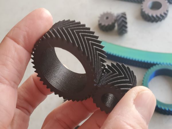
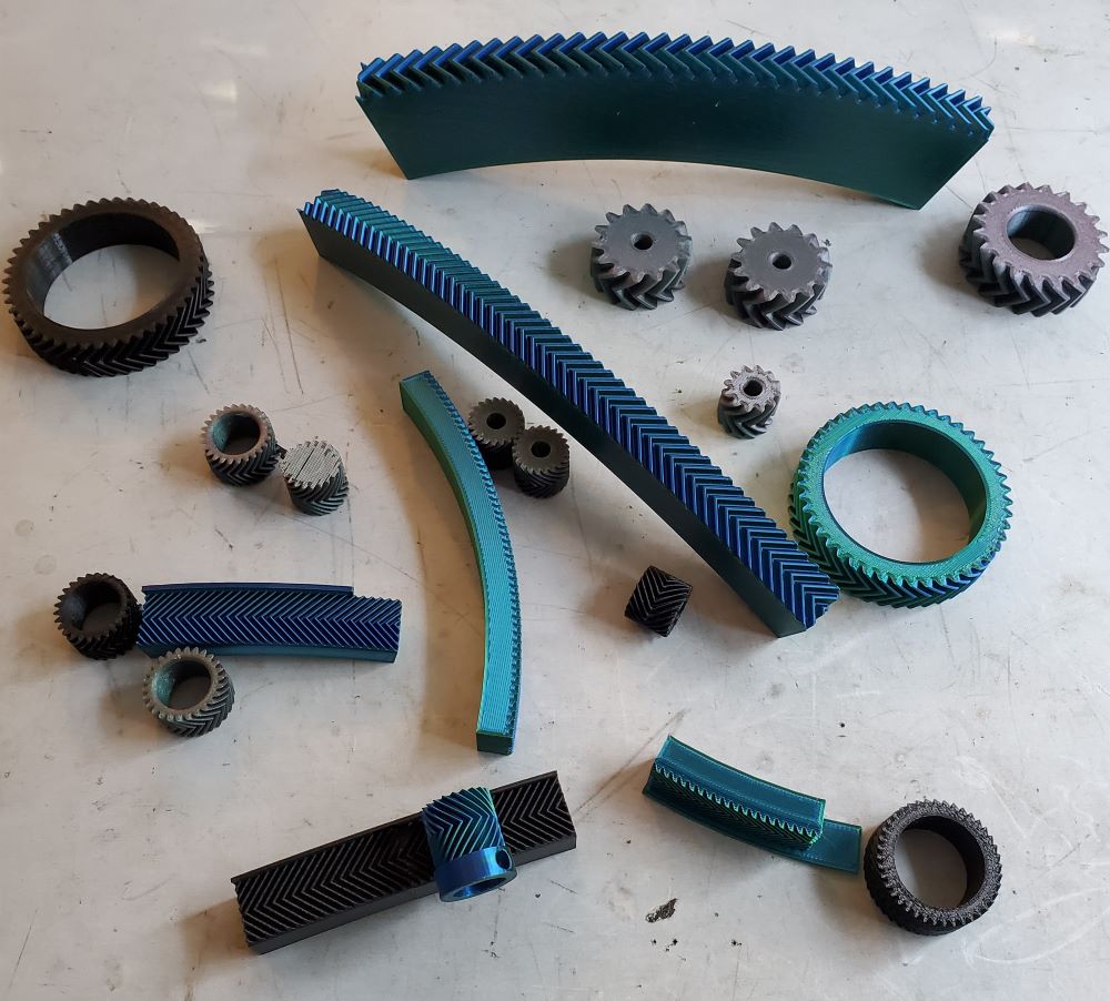
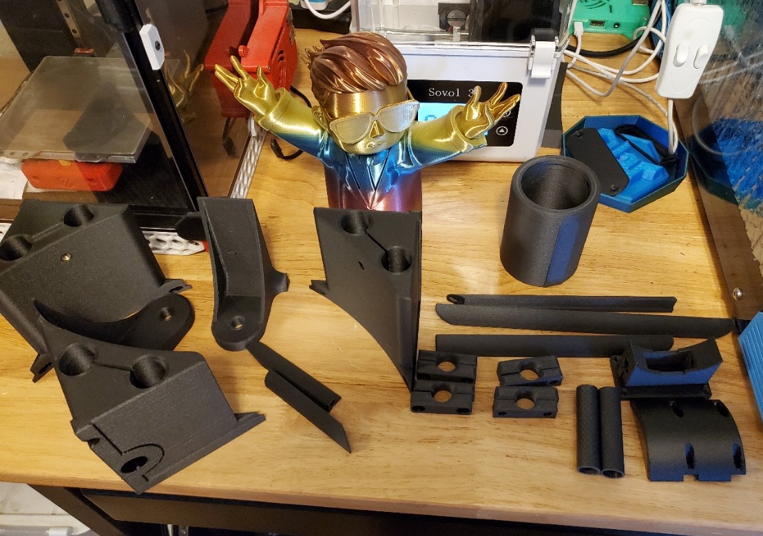
The third image are the first “production” gears printed in Priline Carbon Fiber Polycarbonate (available on Amazon.) I don’t know much about this manufacturer of the structural properties of this material but it prints very nice. I’ll use it for non-structural elements since its much cheaper and more readily available then my preferred material.
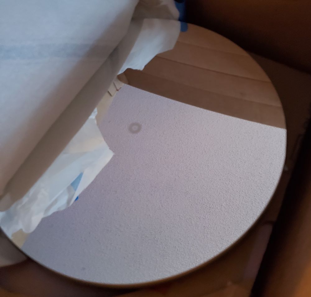
I have also located a mirror set thanks to a member of these forums, 12.5 inch Hubble Optics, and have ordered the carbon fiber tubes.
The mechanical drive design elements and the base designs are finished. Next I will work on the mirror box, forward ring and focuser.
December 21, 2023
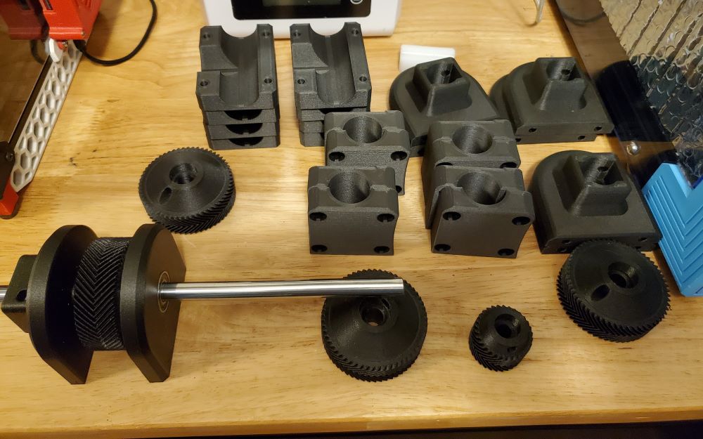
Making good progress on printed part production, super pleased with how they are coming out! Also taking delivery of other parts and accessories, carbon tubes, azimuth bearing, various other hardwares.
December 21, 2023
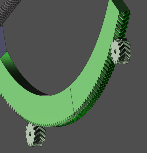
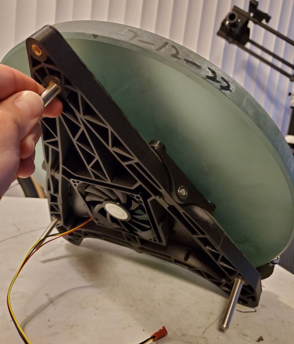
Here’s my strategy for adding damping to the altitude axis. Each altitude bearing/gear is supported by two “roller” gears, one front, one back. These gears have 10mm stainless steel shafts, supported by bearings for consistent, concentric motion. Then, on the inside there is an additional block of Teflon (UHMW) that the shaft runs through. This block is drilled to the shaft diameter but also has a slit so the block can be “clamped” around the shaft. By adjusting the tightness of the Teflon “clamp” I can adjust the amount of friction/damping. This technique works extremely well on the 3D Printed Crayford style focuser I built for my 6″ telescope, so I’m hoping it will also work here. Of course, this case is quite a bit different since there is so much more load then a focuser shaft. I’ll have to build at least the altitude bearings/gears and most of the azimuth base to test. So far at least, I can say the motion is incredible smooth and satisfying just to play with!


January 1, 2024
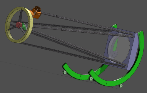
Dry fitting / test assembling the Altitude bearings/Gears. These are looking great and should be plenty strong for the job. There will be quite a bit of hand work to get the joints to fit and smooth the transition between the gear teeth. This was anticipated.
Also test rolling the gears and the results are very promising. Smooth, consistent, damped with no binding!

January 1, 2024
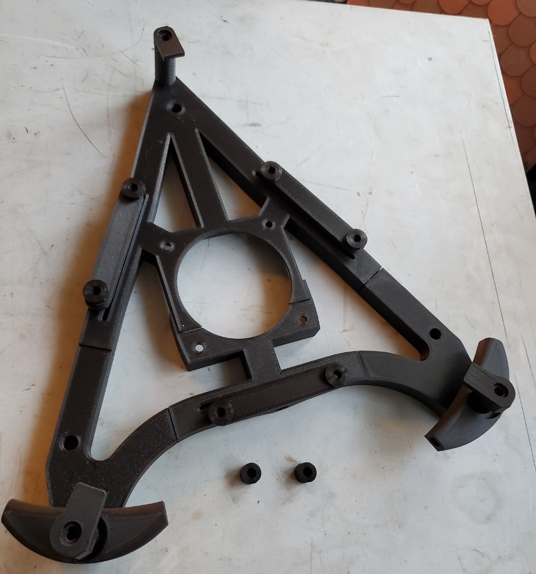
The mirror cell proved quite the design challenge but I think I’ve got a decent solution. I’ll have a 1.6mm sheet of carbon fiber cut, then 3D print the “backbone” which will get bonded on. 6 Points and whiffletree edge supports.
Got all the parts printed but it will probably be a week or so until I see the machined carbon fiber plate.


January 1, 2024
The mirror box has also proved a tricky design challenge what I’m also solving with a combination of 3D Printing and machined carbon fiber sheet. The box has support for the mirror cell as well as the truss tubes.
The mirror box also needs to be broken up into smaller components to fit on the printer. The corner parts alone are like 18 hour prints!


January 1, 2024
Also started working on the forward baffle, just the basic shape and position for now. This is going to be a fun part to design and build. I have some scrap, thin carbon fiber sheet, like 0.4mm, that I think will work well with a 3D Printed backbone/frame type of structure. So that’s about where I am for now. Still plenty of printing to do as well as had work and assembly of parts while waiting for CNC machined carbon fiber sheet parts to arrive.


January 8, 2024
Starting to get some hardware in and sub-assemblies completed.


January 8, 2024
Some of these larger parts really push my printer to the limits and have a bit of warping. I think I’ll still be able to work with those but cosmetically they won’t quite be satisfying. A future re-design, re-print and re-build may be in order but for now I’ll work with what I have. Perhaps my next project will be a new, more capable 3D printer but that’s a thread for another forum ; )
I now have all of the major parts printed and just a few small bits to figure out. The main thing I’m waiting on are my CNC machined, flat carbon fiber parts. Fortunately I have two sources in China making those for about 10% the cost of having them made domestically. Hoping to seem them later this week.


January 16, 2024
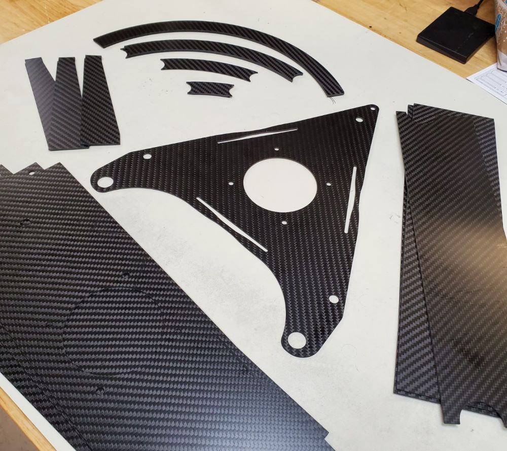
My custom CNC cut carbon fiber sheet parts have arrived! Time to get to bonding/assembling!
January 18, 2024
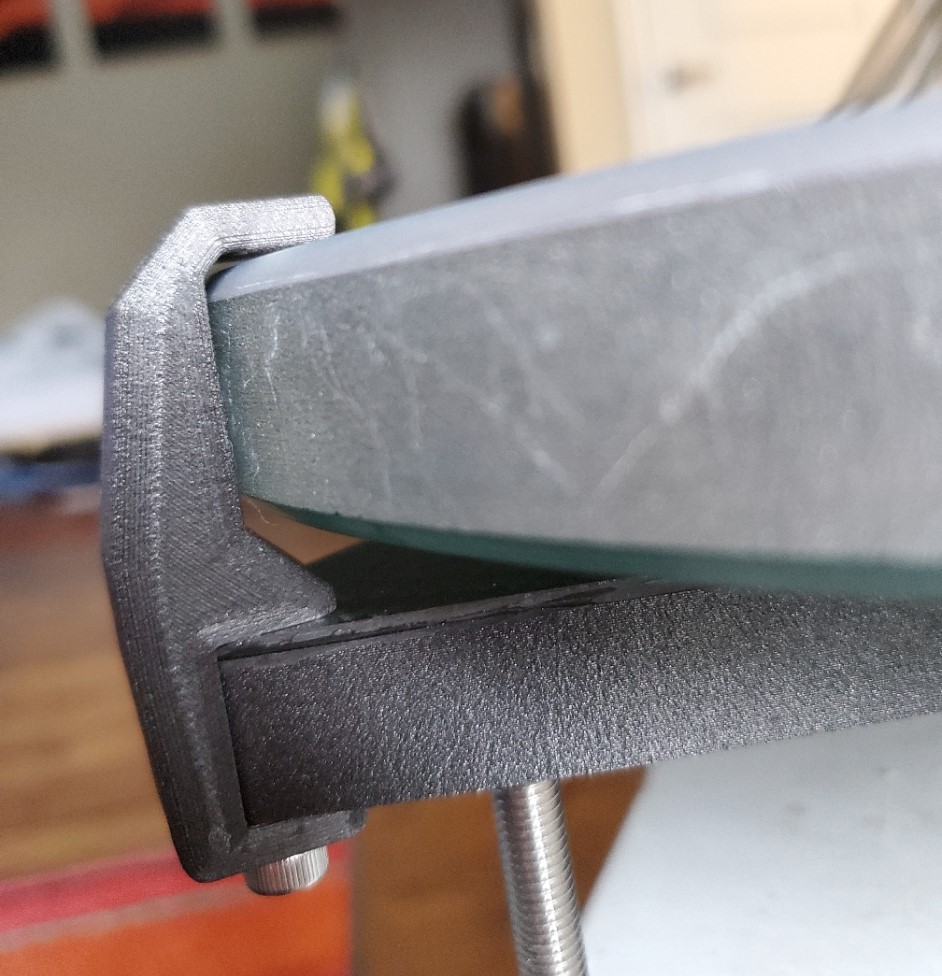
I got the mirror cell assembled and test fit the mirror for the first time. It looks great and should be plenty strong enough but there are some fit issues. The mirror is a bit thinner and larger in diameter then I designed for. The bottom two clips just need to be reduced in thickness about 2 mm. The top clip though will be tricky.


January 18, 2024
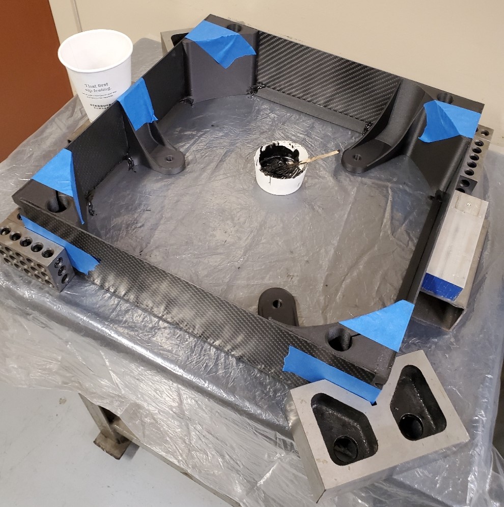
Bonding the mirror box
January 20, 2024
Fixing (adapting) the primary mirror fit issue. I just made an offset clip part that uses the existing mounting hole in the mirror cell.
January 20, 2024
Test fitting the mirror box. The bottom carbon fiber plates of the mirror box are yet to be bonded.


January 20, 2024
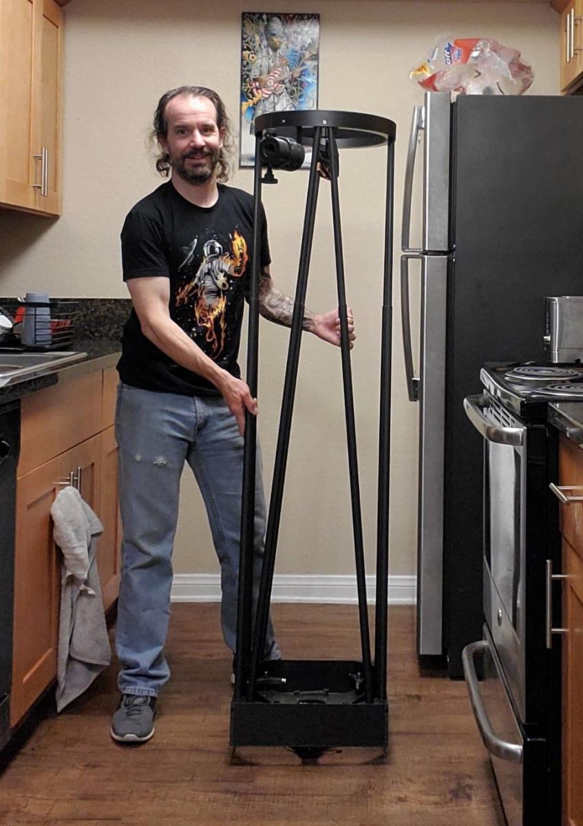
Test assembling the OTA. Bonus Dave for scale (sorry out of bananas.)
Youtube short demo of the Altitude bearings in motion: https://youtube.com/…Svb8-yIFDzaOSTD
Almost 2 months since I started working on this project and I’m finally able to test the most critical aspect, the altitude bearing gear motion. I am happy to report that it seems to be working very well! The motion is smooth, not quite as glassy smooth as one would want, but I think its good enough. Most importantly the motion is heavily damped with zero binding and the telescope stays where you push it to. Also no problems with the gears slipping. The weight of the telescope alone seems to be plenty to keep the gears in mesh.
As anticipated, there is a noticeable bump as the smaller “roller” gears pass over the seams where the larger gears were joined. I will have to get it out for observing to know how big an an issue that is. I’m not sure there is a way around these inconsistencies other then printing the altitude bearings/gears in one piece on a REALLY large 3D Printer. It might be possible to eliminate these bumps with more careful craftsmanship when joining the gear sections together. Perhaps I will continue to experiment and make new gears one day.
The whole structure is still a bit flimsy, mainly because I’ve yet to bond the carbon fiber sheet back plate to the mirror box. Also most of the joints where the truss tubes connect need a bit of hand work to ensure the tubes are inserted all the way and clamped and spaced properly. So, still lots of tweaking and tuning to do. Despite that the telescope seems quite functional. I was able to dial in a quick laser collimation. If it was mounted to the azimuth bearing (and if it wasn’t raining) it would be ready for first light!
January 20, 2024
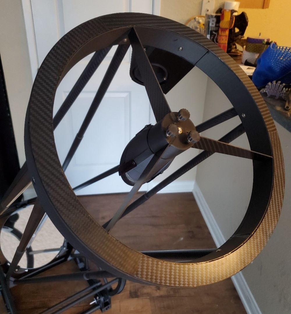
I realized that I never posted pictures of the front end and 3D Printed Crayford focuser.


January 23, 2024
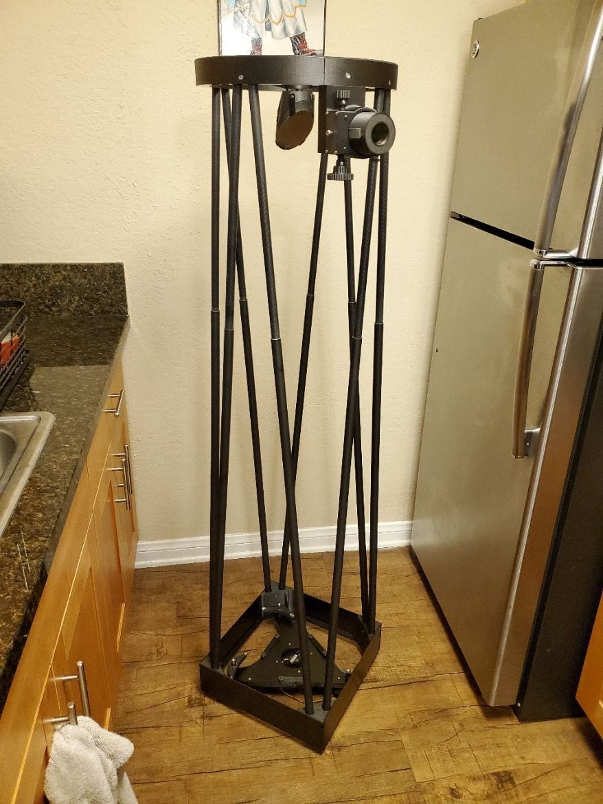
Completed mirror box.


January 23, 2024
Ready for First Light! The telescope and I are about the same height 5’5″. Tiptoes or step stool required for viewing at higher altitude angles unfortunately. One of my goals with this telescope was to be able to observe without “height modifiers” as those can be tripping/falling hazards in the darkness. I can improve this situation by rotating the focuser a bit but that would require redesigning the front ring. I’m thinking I’ll do that anyway to save wight since it came out much heavier and stronger then needed.
Video of movement action – https://youtube.com/…KKVssrWfgeryGmQ
The cheap turntable style bearing works really well (kinda licked out on that) but needs some damping.
About 3 pounds of counterweight is required to balance. Currently the purple and black ankle gym weights will work but I will replace them with a more hidden and/or purpose built option. Also, rebuilding the front ring lighter as previously mentioned will reduce the required counterweight.


January 23, 2024
This is easily one of the coolest things I’ve ever built! Can’t wait to get it out, hopefully a clearing in the clouds tonight. I get such immense satisfaction from seeing my ideas come to life, especially when those things are something practical that I can actually use.


January 24, 2024
First light last night! Still lots of tweaking and tuning to do but it’s showing great promise. Despite the lack of shrouding, horrible lights all around my apartment balcony, quick/dirty collimation, and less then ideal conditions, I was able to see Jupiter, the four Galilean moons, the great red spot (kind/maybe), the moon and a shocking amount of the Orion Nebula!
Attached is a phone-to-eyepiece shot of a tree that I use to align the finder to the telescope FoV and test focus. It’s the furthest daytime object I can see from my balcony.


January 25, 2024
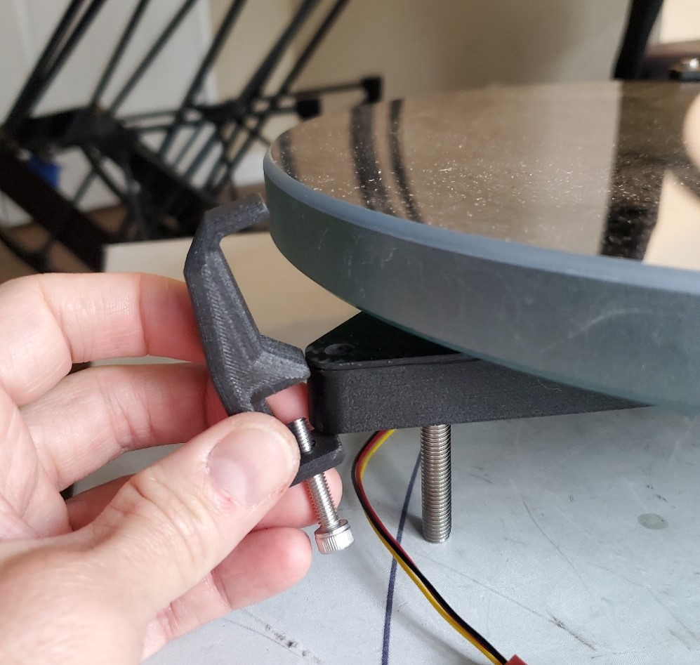
I took the scope apart to work on tuning and other details. Added four UHMW dampers to the azimuth bearing. The amount of damping can be adjusted by tightening/loosening the screws holding the UHMW pads in place (or by removing some of them.)


January 26, 2024
Now with forward Baffle, mirror box cover and perfect height step stool! The forward baffle is made from 0.4mm carbon fiber sheet (single ply, 6K) scraps that I had left over from previous projects (hence the gaffers tape holding the pieces together.) Four 3D Printed ribs hold the shape and four 3D Printed clips hold the baffle to the truss tubes.
And with those improvements I had another great night of observing from my apartment balcony. The motion is much improved and pretty darn close to perfect aside from the overall wobbliness. I was able to split the double stars in the Trapezium cluster no problem. I “discovered” Rigel’s companion star by accident when I pointed the telescope at it to check overall star shapes. The views of the moon are impressive, even when almost full. There seems to be a noticeable increase in contrast of the bright areas compared to my 6″ telescope and others that I’ve looked through in the past.
The last details to figure out are the fabric lower light shroud, a fully setup cover, and transportation bags. A friend of mine owns a sewing shop/business so I will likely hit him up for some help with those.
“Phase 2” of the project is to add motors and an OnStep controller. However I’ve kinda, really been enjoying just pushing the scope around manually the last couple of nights so I feel less motivated to take that on now. One of the original intents with the project, and this thread, was to use 3D Printed gears to drive the axes specifically for adding motors so I guess I need to see that through, haha. No rush with that though. As it currently stands I think this is a very capable, and enjoyable instrument.


February 25, 2024
I added these snap on, clips to hold two of the truss tubes to the altitude bearings | Gears. These help reduce the wobbliness a bit.
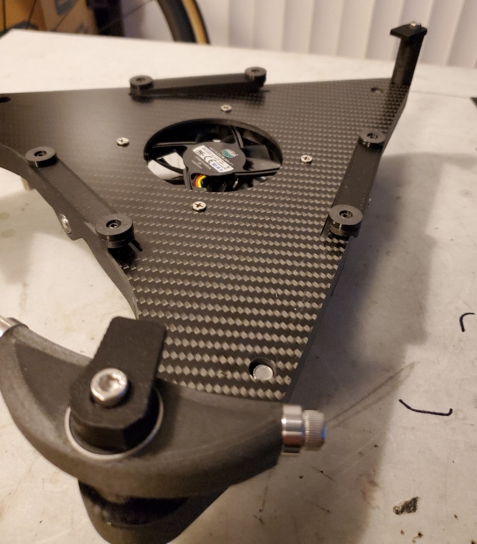
February 25, 2024
The biggest update is that I’ve started working on mounting the guiding motors. I printed prototype parts in PLA, to check to make sure they are going to fit and see if it looks like they will actually work. I think these are going to be okay so I started printing them in the Carbon Fiber PC material that the rest of the telescope is printed from. Very tricky to fit these in here but they do fit. One of the ideas with this mounting strategy is that the motors simply clamp to the base carbon tubes. That allows me to just loosen and slide the clamps to disengage\re-engage the motors. I’ll add some thumbscrews so that can be done without tools. In practice, I think this is going to be a bit fiddly and not ideal. However I don’t think its a feature I’ll need all that often so some degree of fiddly-ness should be tolerable.
I hope to have this all up and running by the next new moon in a couple of weeks. I still need to get the telescope out under some proper dark skies! Fingers crossed for the weather.


February 27, 2024
I got the Altitude motor printed and installed. My new printer is working great! Based on experience with the PLA prototype part, I doubled the thickness of the clamp area where joins to the base. This provides much more friction and should help keep the motor from slipping when I don’t want it to. A large, ratcheting thumb screw provides tool-less adjustment for motor engagement to change from tracking to push-to mode. The carbon fiber twill pattern on the bottom of the print is thanks to the texture on the PET build plate. It’s fake carbon fiber patter on real carbon fiber printed part, so it kinda works haha.


February 27, 2024
I redesigned how the azimuth motor mounts. It was clear, and was pretty obvious early on, that it would be very difficult or impossibly to assemble the large azimuth gear circular and concentric enough to the main azimuth bearing. Also there is a lot of radial play in the azimuth bearing. This of course means that it would be impossible to have the azimuth gear and pinion mesh consistently as they rotate around. At best there would be a “tight side” and a “loose side.”
I also needed a better way to engage and disengage the gear mesh to disable to motor for manual push-to operation.
This is what I came up with. I used an extra bit of linear rail I had left over from my 3D Printer upgrade project to allow the motor to translate in one axis, while constraining it’s motion in all others. I then spring load said axis so there is constant tension holding the gears in mesh as they rotate around and the “effective” diameter of the large gear changes. To disengage, I simply slide the motor back and will secure with a pin. So far, at least on the test bench, this seems to work quite well! The motor (and motion) seems quite smooth and you can see the linear rail sliding a bit back and forth as expected. I will have to get the whole telescope assembled to dial everything in. I might need more tension in the spring, but that is adjustable with this design.


March 2, 2024
https://youtube.com/…gng1E60aK4OHLVa
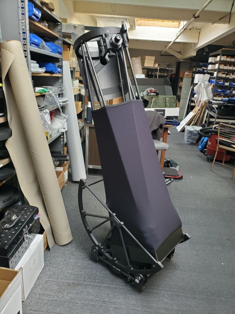
I made a visit to my buddy’s sew shop to get the last major part of the telescope made, the light shroud. It’s made from thin neoprene which is actually kind of overkill, but he had some extra so we used that.
March 6, 2024
I got the electronics setup and working. The go-to pointing isn’t very accurate but tracking is pretty good. This is consistent with my previous experience with an OnStep controller that I installed in my Harmonic Drive mount.

March 9, 2024
The weather held for a very nice evening of observing in the California high desert last night. Not too cold either. Seeing was probably just average at best but it was good enough to finally put this telescope to work. And, wow! I am super pleased, impressed and satisfied. I made a decent jab at the “Messier Marathon”, finding pretty much all the Messier objects that were visible by midnight or so. I wasn’t quite feeling like pulling an all-nighter to see them all. I’ll just wait until summer for the rest.
The go-to system had issues, mostly because the azimuth gear kept snagging on the mat I set on the ground under the telescope. I didn’t anticipate that but the fix is easy, just taller feet and proper camping staked to hold the mat down.
That actually worked out though as I was forced to learn star hopping real quick and was able to find every object I was looking for. Kinda proud of myself for that. Having Stellarium on my tablet definitely helped, especially when identifying all the galaxies around Leo (there’s so many of them!) I’m finding that I really enjoy just pushing this scope around.
Highlights of the night include:
- The contrast on the Orion Nebula. That dark part in front really stood out, as well as all the surrounding gas.
- The Whirlpool Galaxy looked pretty striking. I could kinda, maybe make out the spiral structure but only just. Perhaps with better seeing and or a more clear night. This sight tends to be a bit hazy as its down in a desert valley. I’m definitely looking forward to coming back to this object in the summer when its warm enough to go up in the mountains.
- Accidentally “discovering” the planetary nebula NGC 2438 inside the Open Cluster M46. There are lots of open clusters in the Messier catalogue and it can feel pretty repetitive to look for them all. Glad I did though as this one held a little surprise.
- Globular clusters are always amazing, even with low on the horizon.
I’m working on a short film to summarize this build and show some details. Hope to have that finished up in a few days.
